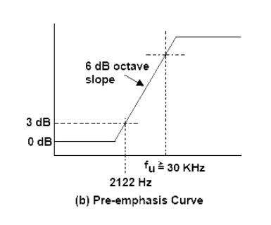
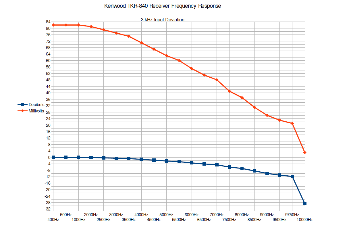
Transmitter Audio Response and Why it matters The audio response of a single transmitter system is not terribly critical. As long as it's reasonable and not slanted to much to one end of the audio spectrum or the other, your audio will be acceptable. I know there are many audiophiles that take great pains to make their audio sound as perfect and HI-FI as possible within the confines of 5 KHz of deviation. For the average repeater user in the field the impact is minimal. In the case of simulcast, not only does the audio response of the system need to be reasonable but all the transmitters must be as close to being exactly the same as possible. Typically when dealing with commercial radio equipment such as a Motorola Quantar or Tait TB8100 you usually do not need to worry if the audio response among the transmitters is going to be the same or not, assuming all your settings are correct. When using radios that were not designed to be simulcast transmitters is where you need to take a closer look at things as far as the audio response is concerned. Speaking from an audio quality perspective, your transmitters having a flat audio response will ensure that you have audio with not too many highs or lows in the received audio. The audio that gets delivered to the transmitter from the RTCM/Voter Board is Pre-Emphasized. This means that usually starting at about 2100 Hz the audio level increases as the audio frequency rises. This is a 6dB increase each time the frequency doubles also known as 6dB per octave increase.This is complimented by De-Emphasis performed on the receiving end. The reason this is done is to increase the intelligibility of the voice audio and reduce noise on the received transmission by reducing the amount of high frequency noise due to static on a transmission that isn't full quieting. Even if you are using all commercial transmitter that are designed to be simulcast transmitters, testing them to see what their audio response curve is and that they all match is always a good idea in my book. There are two ways that this can be checked. Method #1 Test with individual audio tones I have performed this method and it gives excellent results but is a little more time consuming. You will need a sine wave tone generator that you can set the tone output frequency to what you want. You will also need a radio with flat audio output fed into an oscilloscope or a radio service monitor with a mod scope display. An easier to read way is you use an AC voltmeter on the demod out of your service monitor or the radio you are using to listen to your transmitter that has a flat audio output. What you need to do is generate different tones frequencies, inject them into the transmitter and look at the result on the scope. These are the test frequencies I use: 1. 100 Hz 2. 200 Hz 3. 300 Hz 3. 500 Hz 4. 800 Hz 5. 1250 Hz 6. 1500 Hz 7. 1750 Hz 8. 2000 Hz 9. 2250 Hz 10. 2500 Hz 11. 2750 Hz 12. 3000 Hz 13. 3250 Hz 14. 3500 Hz 15. 3750 Hz 16. 4000 Hz 17. 4250 Hz 18. 4500 Hz 19. 4750 Hz 20. 5000 Hz So this is twenty (20) readings that span the audio frequency spectrum we are worried about. This can be done with less test points but the more test points you have the more sure you can be. Using this method, you can use an AC voltmeter to take your readings. Run all your transmitters through this list of tones and write down the results and compare them to each other. Ideally, your AC voltage reading when comparing the reading for each tone frequency across all the transmitters should remain within +/-.01 volts. Another thing to take note of is how the voltage readings of all the tones tested on one transmitter compare to each other. The readings should be pretty close to each other. You may see them start to fall off a little bit toward the upper end but that is to be expected. If the readings look to be close to each other across the whole range within the testing of a single transmitter, this indicates that you do have a reasonably flat audio response. Here is a graph of the measured audio response of a Kenwood TKR-840 repeater:
Method #2 The Square Wave Using this method you cannot use a voltmeter, you need to see the waveform on a service monitor or a scope. This way is much faster than the one described above in checking if you have a flat audio response and if all your transmitters are the same. You will need a signal generator that can generate audio square waves. Specifically a 450 Hz, 50 percent duty cycle square wave. The entire test using this square wave is simple, inject a 450 Hz square wave, and see if the same thing comes out! More specifically that the waveform that comes out of the transmitter is a nice, sharp cornered square wave with a level flat top not slanting up or down on the either side. If a nice clean square wave comes out of the transmitter you know that your audio response is flat up to 5 KHz and if your other transmitters have the same response too then everything is OK and your transmitters are all the same. Now, why this works has to do with what a square wave is composed of. A square wave is a complex waveform composed of odd order harmonics. So, here is why we use a 450 Hz square wave: 1st Order Harmonic (our chosen frequency to generate) 450 Hz 3rd Order: 1350 Hz 5th Order: 2250 Hz 7th Order: 3150 Hz 9th Order: 4050 Hz 11th Order: 4950 Hz Essentially, a 450 Hz square wave is testing our audio response simultaneously at these odd order harmonic frequencies. If any of these frequencies were being amplified or attenuated, the square wave would come out of the transmitter distorted. As you may already know with harmonics, every order after the first order decreases in power. Going past 11th order in this case isn't relevant because we are starting to go past our audio response frequency limit. Here is a visual representation of what is going on:So as you can see, a square is simply composed of these odd order harmonic sine waves. If the frequency response was not flat in the transmitter, we would see distortion of the square wave on the output.