This is a small project I have been working on for the past 6 months. This was born out of diminishing stores of parts to build my original 9.6 MHz PLL board and the PCGM. I originally came up with a rather simple solution to provide the needed 9.6 MHz for the RTCM and Voter Board. This idea was my RTCM/Voter Board GPS Module version 1.0. This unit utilized a dual timepulse output GPS unit that was able to provide the 1 PPS, NMEA Data and the 9.6 MHz to the RTCM or Voter Board. This worked very well, but soon after I announced it's creation, I received requests to make something that would also provide a GPS locked reference for a transmitter. Not only that, it would also need to have the ability to provide a frequency agile reference to accommodate radios that were modified to accept an external reference such as a Motorola Maxtrac. After much thought about how I would do this, without it being overly complicated or expensive, a friend of mine mentioned that QRP Labs had recently released a device called a Progrock 2 that could be GPS disciplined with two independent outputs. Here is a picture of what this device looks like:After bench testing this device I determined it had enough precision and accuracy to be the heart of my device. This caused me to redesign most of my device and give it version number 2.0. I was certainly glad to have found the Progrock 2 because it made my job 100 times easier. This meant I did not have to write code for a micro-controller (I was going with an Arduino Nano at the time) and discipline my own synthesizer. In fact I was going down a similar road that QRP Labs took for the Progrock 2. The main difference was, I was going to GPS lock a 25 MHz oscillator and write a program (more like heavily modify and existing one, lets be honest here!) to be able to enter the desired frequencies into the Si5351A synthesizer chip, which also happens to be the same device the Progrock 2 uses. The parts count and cost of my idea would have been much higher than the cost, plus shipping of the Progrock 2 so it was no contest which method was better overall. After a few revisions, and PCB error corrections, I am currently on version 2.04. The version pictured below is a version 2.04 device, I just did not feel the need to order new face-plates to simply add the number "4" to them.
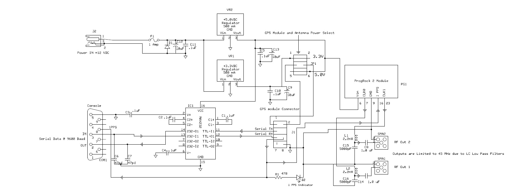
The front of the device has two, SMA Female connectors for the two independently configurable RF outputs. These outputs go through low pass filters that can be configured to your specific application. The low pass filters are there to suppress any harmonics produced by the device. There is also an LED indicator of the 1 PPS signal. This LED, is tied directly to GPS modules 1 PPS output through a resistor. The DB9 connector outputs the Ublox GPS modules NMEA data as well as the 1PPS which is also required by the RTCM and Voter boards. The wiring of the DB9 connector is identical to the BG7TBL unit so this can function as a drop-in replacement for it. The DB9 connector also allows you to use the Ublox software to monitor and configure the GPS module inside it as well. This unit will provide a simulcast site with 1 PPS, NMEA RS232 Data, Transmitter Frequency Reference programmable up to 160 Mhz (Depending on the configuration of the LP filter), and the 9.6 MHz for the processor on the RTCM or Voter Board. So far, I have six of these units built and installed at six of my simulcast sites for real world system testing. As of now, the results have been very good. I have completed my field testing of this GPS unit and it is ready for prime time. If you would like a fully assembled and tested unit, please contact me at kc2irv@gmail.com If you wish to build your own the schematic for my portion of this project is pictured below.
AllstarLink Amateur Radio Voting and Simulcast
Using the Voter Board and Radio Thin Client Module