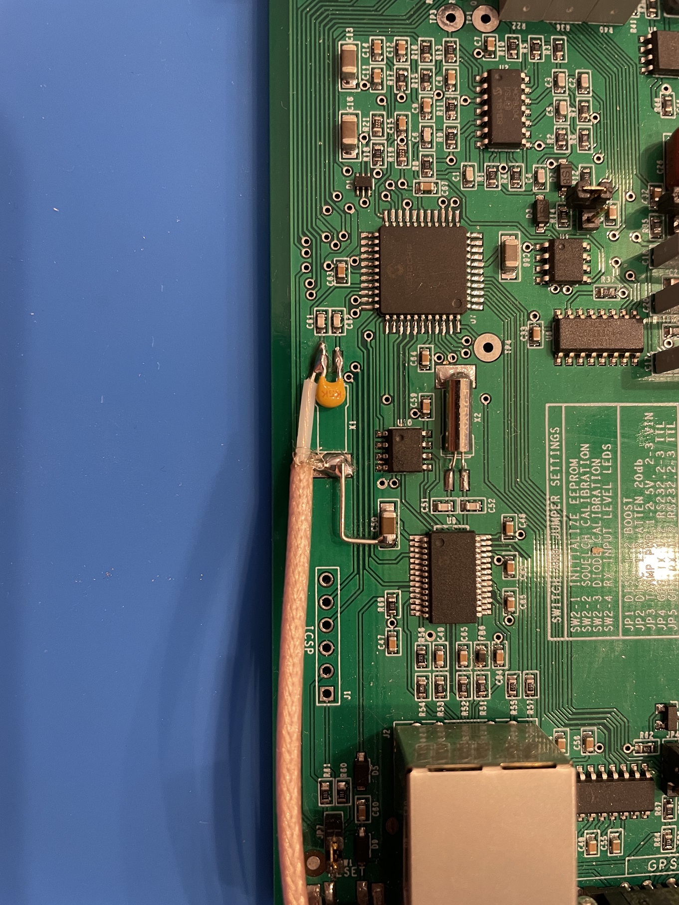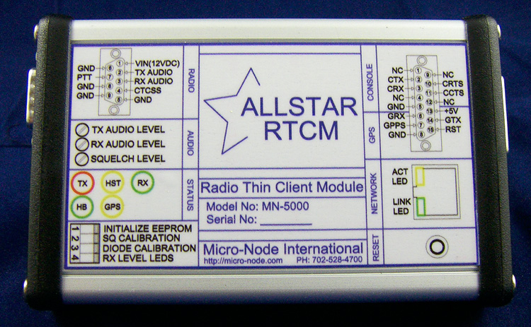
This device is the commercially available, service mount version of the voter board. It is available for purchase from the Micro-Node Website. It is the functional equivalent of the voter board in a smaller package. You can run both RTCM's and Voter Board's in the same simulcast system with no issues. As with the Voter Board, in order to Simulcast you need to modify the board to accept a 9.6 MHz reference to precisely time the microprocessor on the board. If this is your first time setting one of these RTCM's up, I would suggest you save the 9.6 MHz input modification until after you get the RTCM up and working properly. All of this assumes you have Allstar up and working and have you voter to conf file configured. Here is the quick start guide for the RTCM, don't worry, I will go into detail on each step later. 1. Power on the RTCM and connect it to a network that has DHCP. 2. Find the IP address of the RTCM and login using Putty with Telnet on port 23 3. Login to the RTCM, First time login Username "admin", Password "radios" 4. Configure the GPS settings and a static IP address if you wish, see the Examples Page. 5. Put in the IP address of the host computer in the 2 - Voter Server Address setting. 6. Once the GPS and HOST LED's light up solid your RTCM is successfully connected to the host computer and is ready to be used. Of course this is a very condensed version of how to get the RTCM up and running. A more comprehensive version of a "quick start" guide will be coming soon. RTCM 9.6 MHz Input Modification WARNING!!!! You perform this modification at your own risk. This modification may void the manufacturers warranty on the RTCM. Improper handling and failure to mitigate electro-static discharge can damage the unit while you are working on it. There is a crystal labeled X1 on the edge of the RTCM's circuit board next to the PIC. This crystal is the 9.6 MHz crystal that provides the clock to the PIC. In order to successfully simulcast with the RTCM this crystal must be removed and a GPS derived, highly accurate source of 9.6 MHz must be injected. The modification for this is fairly simple to do, but you need to still be careful and have a steady hand. Here are the steps I follow to do this with the assumption you have already taken the unit apart: 1. Remove the crystal from the board and save it 2. Solder a .1 uF capacitor across the two pads where the legs of the crystal were connected. 3. Using a piece of RG316 coaxial cable, solder the center conductor to the pad that is closest to the edge of the board where the crystal legs where soldered and where you now have a .1 uF soldered across. 4. Solder the braid of the RG316 to the large pad where the case of the crystal was soldered to. 5. Connect a small wire from a ground point to the large pad where the RG316 Braid is now attached to complete the ground connection. In the case of the newer blue solder mask version pictured below DO NOT solder a wire to the capacitor to the right of the crystal case solder pad. This will cause the RTCM to not boot up and the Ethernet interface will no longer work. Find the next closest point that is connected to the ground plane to solder the braid of the cable to. Here are pictures of what the completed modification looks like. The picture with the board with the green solder mask is the older version of the RTCM. The one with the blue solder mask is the newer 2022 version. There are differences between the two boards that need to be taken into account. These pictures show examples of how the 9.6 MHz injection modification can be done.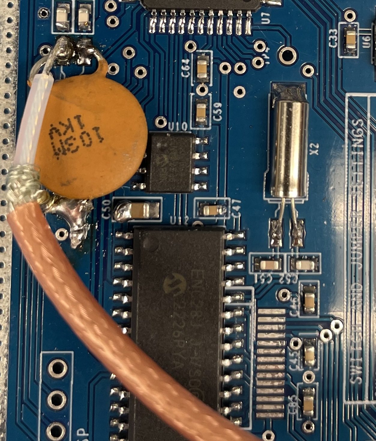
With this modification completed, you will need to apply an external source of 9.6 MHz to the RTCM. With that 9.6 MHz applied, when you power your RTCM on it should boot normally.