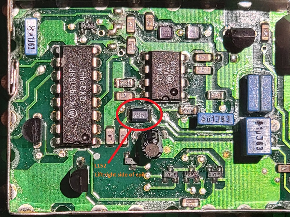
The Motorola Maxtrac I have made this a separate page since it is out of the ordinary but I believe it to be a viable option for a low cost simulcast transmitter. These radios are pretty old but still seem to be available everywhere and can be had for as little as $20. To make this radio a viable simulcast transmitter two modifications must be done: 1. Modify the radio synthesizer to accept an external 14.4 MHz reference 2. Modify the RF power control circuit for manual adjustment. All this assumes you have a Maxtrac with the 16 pin accessory connector option. If you don't, an additional modification must be performed which I will elaborate on in the future. For now let us assume you have the 16 pin accessory connector version. Modifying the Maxtrac to accept an external reference is rather easy. In the synthesizer circuit which is located on the board on the top of the radio you will find a 14.4 MHz crystal, remove that crystal. Next you will find a green colored coil at the front of the radio (it kind of looks like a fat resistor), this coil is L151 (L152 for the M120) on the schematic. With the front of the radio facing you, use a soldering iron and lift the right side of the coil off the board carefully. Take a piece of RG316 coaxial cable and solder the center conductor to the end of the coil you lifted and solder the braid of the cable to the shield next to the coil. On the other end of the cable put whatever connector on it that works best for you, in my case I like to use BNC's. I have documented this modification in a YouTube Video to make it easier to understand. The reason you do not inject your 14.4 MHz into where the crystal was loacted is mainly due to the amplifier on the output of the crystal oscillator which has a lot of gain so you can you can't inject you signal there otherwise is just over drives the transistor amplifier that is part of the oscillator circuit. Now for the other side of this the reason you cannot inject your 14.4 MHz reference directly into the PLL chip is due to noise and possible harmonics. If you bypass this coil or go directly to the PLL chip, you may experience the PLL chip randomly losing phase lock. The reason you need to insert your signal through that coil is because that coil and another capacitor form an LC low pass filter with a cutoff frequency of about 17 MHz, then the signal is fed into Pin #1 of the PLL chip. So feeding the 14.4 MHz reference into the one side of that coil is the perfect place to do it and provides flawless results. Motorola External Reference Modification Video Motorola M120 This radio is extremely similar to the Maxtrac and is pretty much a basic version of the GM300. This radio is a very good option as well since its pretty much the same when it comes to its PLL and RF sections. The one difference that someone who is doing a simulcast conversion on right now has mentioned is that many of the components on the board with the PLL circuit are surface mount, including the coil L152 that you need to lift one side of and inject your 14.4 MHz reference. Here are some pictures that he was able to take of what the coil looks like and where it is as well as the schematic.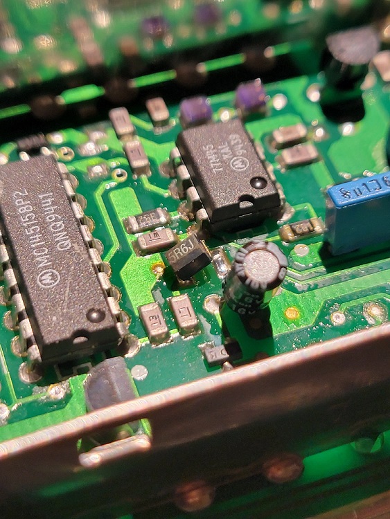
My recommendation to provide your 14.4 MHz but also the 9.6 MHz you will need to provide at the same time to the RTCM/Voter Board is the Leo Bodnar GPS oscillator with dual outputs. Leo Bodnar Dual Output GPS Oscillator This unit can be programmed to output both the 14.4 and 9.6 MHz references in a single unit. Note: There is a small DC voltage on the outputs of this reference oscillator, you need to use something like a .1uf ceramic capacitor between the Leo Bodnar oscillator and the equipment it's feeding to block the DC. If not, you run the risk of damaging the radio and/or the RTCM/Voter Board.
The second modification deals with an unadvertised "feature" of the Maxtrac that is a hard coded power fold back timer that, if you get a good long conversation on your system, it will cause the Maxtrac to gradually fold back its TX output power until it shuts it off completely. This is only reset by the release of the PTT line to the radio and then the timer restarts. You can disable this by performing a modification to the power control circuit using some resistors and a small pot to manually control the power output. Luckily this modification is well documented on Repeater Builder. Repeater Builder Maxtrac Power Control Modification Once this mod if done you will no longer be able to control the power output using the Motorola RSS software. You will only be able to control the TX power output of the radio using the pot you installed. With these modifications completed and your power output set, you can wire up your RTCM/Voter Board to the 16 pin accessory connector of the radio. This requires on 3 connections: 1. PTT 2. TX Audio IN 3. Ground PTT is wired to pin #3 (Active Low) TX Audio IN is wired to pin #5 (Flat TX Audio) Ground is wired to pin #7 Here is a diagram of the accessory connector, ignore arrows on the diagram:Now your radio should be ready for simulcast operation. I would limit the radio output power to no more than 25 watts for the high power model and no more than 10 watts for the low power model and in all cases I would highly suggest using a fan to keep the heat sink cool. In my opinion a better option is to the run the radio at 5 watts and use it to drive an amplifier. If you choose to use Maxtrac's you should make all the transmitters Maxtrac's so that the audio response is the same among all the transmitters.
Maxtrac with a 5 pin accessory connector
Sometimes you cannot find a Maxtrac with the 16 pin accessory connector. This isn't a big problem but it will entail some extra work. The issue is, you need a place where you can inject flat TX audio. There is a modification that is well documented on Repeater Builder that will walk you through this.
In short, this modification injects audio into a certain place in the radio's audio chain and brings it out of the radio on an unused pin on the microphone jack. With this mod, your TX audio, ground and PTT would all be done using the mic jack on the front of the radio.

Repeater Builder - Modify a Maxtrac with no 16 Pin accessory connector for Flat TX audio
Programming the Maxtrac, M120 and GM300
These three radios may be a challenge for some in this day in age. The software needed to program and align them will only run in MS-DOS or a substitute thereof. Some solve this issue by keeping a Pentium II or slower machine handy loaded up with MS-DOS and the software just for programming these older radios. There is a more modern way of doing it that does work well and can be done under Windows 10 (I haven't tried it on 11 yet).
The solution I speak of is a little virtual machine called DOSBOX. You can download DOSBOX HERE. To accomplish the programming of your radio, you will need a few things:

1. Windows 10 Computer with DOSBOX installed
2a. An FTDI USB to Serial adapter. Something like this will work.
2b. A multi radio programming cable like this which has USB built in already will work too.
3. And of course, a radio to program

There is someone who has a webpage with step by step instructions that you can follow to get everything up and going.

Setting up DOSBOX to Program a Motorola Maxtrac or GM300

Here is a short YouTube video I made about the subject as well. The video says programming with Windows 7 since I made this video awhile ago but the there is no real difference between setting it up on Windows 7 or 10. This video is also only about the GM300 but its all the same for the Maxtrac and the M120.

Programming the GM300 on Windows 7 YouTube Video

When it comes to programming these radios in the amateur radio bands, you will find some radios do no cover amateur radio frequencies and if you try to program an amateur frequency into them it will error out. All these radios are capable of operating pretty far outside of their band limits within reason of course. If you have one of these radios, for example with a 450 to 470 MHz spread. you can program it down into the amateur band by entering the frequency with the SHIFT key on your keyboard depressed.
EXAMPLE
Desired frequency: 449.875 MHz
Actual characters entered with the shift key depressed: $$(.*&%

You still need to decimal point in the frequency so to enter the decimal point you will need to release the shift key momentarily to enter it. Once the frequency is entered in this way and you press ENTER you will see your desired frequency appear in normal numbers. You can now write the codeplug to the radio.
This same trick also works on the Motorola GR1225 repeater as well.

On some radios that have tunable coils in their receiver front end you may need to tune these coils for maximum receiver sensitivity. This will depend on how far out of the radios original band you go. Tuning of the RX front end coils should be done with a proper set of plastic tuning tools.
With the transmitter, you may find for example a 450-470 MHz radio that is programmed into the amateur band you may notice a decrease in transmitted output power. Usually the output power decrease it not enough to make a difference. If the radio is programmed far enough out of its original band the TX power output decrease may be more than you want, this sometimes can be solved by squeezing some of the coils in the Power Amplifier section. These coils are usually pretty obvious because they are typically spread apart somewhat. Squeezing each coil a little bit and testing the power output at each point. What the squeezing of these coils does is lower the resonant frequency of the circuit to more closely match the frequency you programmed into the radio. BE VERY CAREFUL DOING THIS! Go slow and if you are going to do this, do it with the radio connected to a power supply with a current meter and keep watch for a sudden increase in current draw. If you see the current draw spike you most likely have gone too far and should put the coil you changed back to where it was.