This device is a redesign of the original VOTER board, here are pictures provided by Matt Krick.
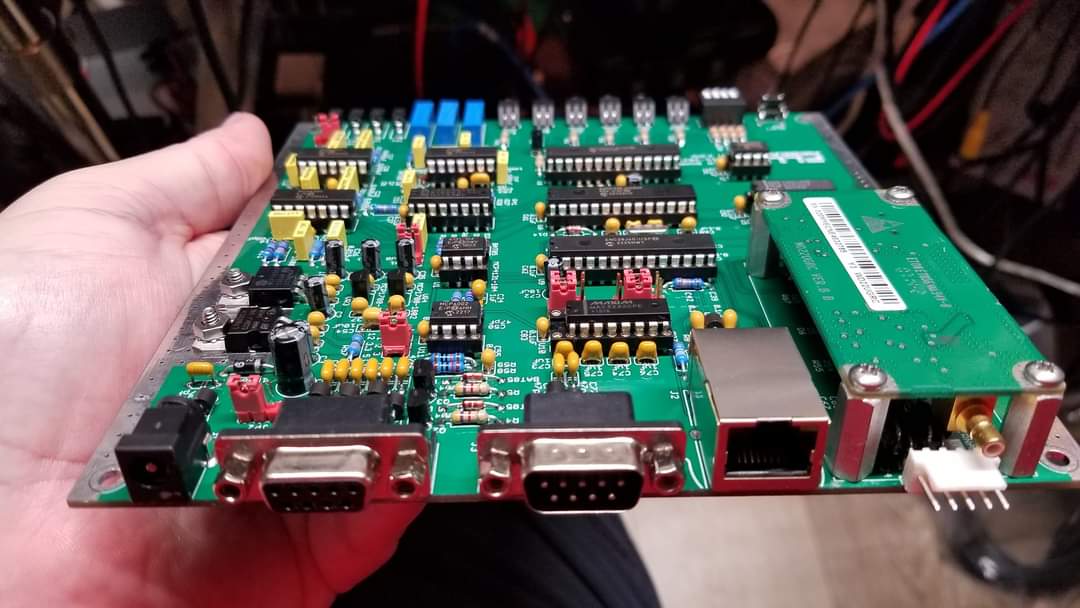
This was something I was going to undertake but I was beaten to it by Matt Krick, K3MK. He has graciously provided all the information to build the PCB's and the front and back case cover plates for the Hammond case the board was designed to fit into. The major improvement this redesign incorporates is the ability to add a GPS module to provide the required NMEA data, 1PPS and 9.6 MHz to the processor for voting and simulcast. The right GPS module with two time pulse outputs can provide NMEA Data, 1PPS and the 9.6 MHz clock for the PIC. So far the unit that allows these three signals is rather expensive. The one that is commonly available now is the Ublox RCB-F9T GPS Board. There are much less expensive modules that will provide the NMEA data and 1 PPS for voting operation but not simulcast.
UPDATE - June 12th, 2026
Since the time I first published this page on the Thick Client Module, K3MK has been busy with updates. At the moment he has released the information for his latest version being the Thick Client Module V2.0A. I am looking forward to building this and testing it. This version has options for an internal GPS unit like the past versions and also for a GPS disciplined OCXO with an output for your repeater frequency reference. K3MK has all the information available in a documentation package he has released.
K3MK's Thick Client Module Version 2.0A Documentation
This unit is a complete, self contained solution whcih K3MK has worked very hard on and I thank him for all his effort in this project.
When I am able to build and test a unit, I will most likely create a dedicated page to the 2.0 version due to the updates and differences.
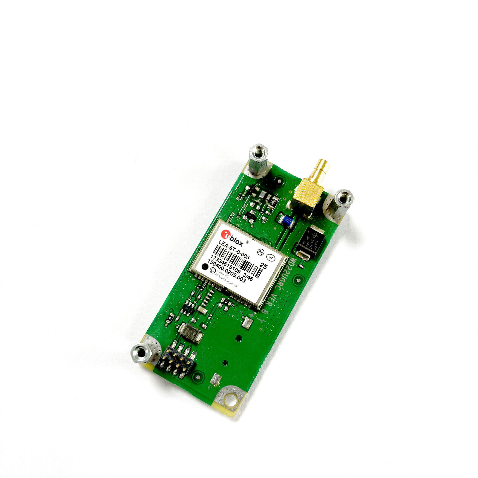
The photo below is an example of one of the boards you can use that provide only NMEA Data and 1PPS.
This is a Ublox LEA-5T GPS Board. These are currently available on Ebay for a very low price.
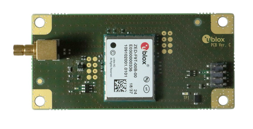
This unit pictured below is an RCB-F9T unit will provide all three signals for simulcast operation.
These can be purchased from Digikey at the moment. Other suppliers also sell this particular unit.
NOTE:
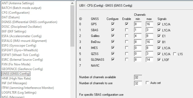
On newer GPS receivers such at the Ublox ZED-F9T and the LEA-M8T you may have an issue with the board accepting the GPS signal. This has to do with the software for the board currently only supporting NMEA sentences from the U.S GPS constellation. When it comes to the Ublox units, this is easily solved by going into the GNSS settings and turning off the other constellations in the receiver.
learn more about the different GPS constellations
GPS Modules such as these typically use an SMB connector for the GPS antenna. Unless you have a cable with this connector on it that goes to a GPS antenna, you may want to adapt it to a more useful connector such as an SMA or an N connector. An SMB to N-Female pigtail is useful and can be had from Amazon. Some antennas come with a pre-installed SMA male connector, in this case an SMB to SMA Female adapter will work and once again, can be had on Amazon.
NOTE: These modules typically expect an active antenna that is most commonly powered by +3.3 or +5.0 VDC.
On this board, there is a provision made using a jumper to select between these two voltages for the antenna being used. Active antennas use an LNA (Low Noise Amplifier) built into them to make up for the coaxial cable loss and maximize the number or satellites seen by the GPS receiver. Take note of the voltages your antenna will tolerate, some antennas that use +3.3 VDC may work for awhile on +5.0 VDC but won't tolerate the over voltage for long and possibly fail prematurely. Conversely, an antenna that is only designed to use +5.0 VDC may produce poor performance or not work at all with +3.3 VDC. In my experience, most active GPS antennas will allow proper operation using both voltages.
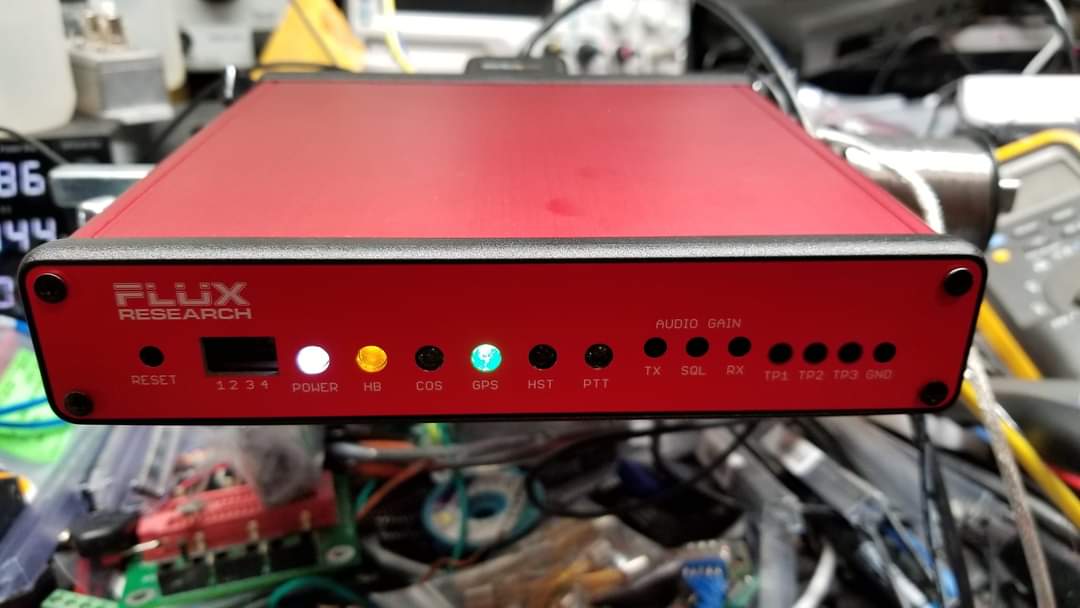
The Thick Client Module is meant to fit into a Hammond enclosure, part# 1455R1601 and can also be mounted inside the Motorola Spectra desk enclosure. Another major improvement is that the GPS data levels that can be input externally to your board can be RS232 or TTL using on-board jumpers to select which, so no need to use an external level shifter. Another handy feature he has added, is an option to see the serial output of the GPS unit on the Console connector. This is helpful for troubleshooting GPS issues. Before I go any further, the complete documentation package can be downloaded using the link below.
Download the Radio Thick Client Module Documentation package
The documentation package contains a complete parts list using mostly Digikey part numbers, so ordering the components to build the board should be fairly easy for everyone. I have completed one board and I am currently testing it with various GPS boards. I have found the Ublox based boards to produce better results and have more sensitive receivers. One of the tools I use to evaluate a GPS receivers performance is a program called Lady Heather's Disciplined Oscillator Control Program. This program is very handy and I recommend having it in your tool box.
NOTE:
The 74HC4053N device seems to be out of stock in its through-hole package at the moment from the major parts houses like Digikey and Mouser. Amazon and Ebay have them, if you are willing to wait a little longer for them to ship. Another Alternative that I have employed, is using the SMT (SOIC) version of this device which is available from Digikey HERE. Then, using an SOIC to DIP adapter you can make it compatible with the board. Both devices have an identical pin-out so you just need to solder the device onto the adapter and plug it in. The parts list contained in the documentation contains the Amazon link for this device in its through hole package. If you think you may want to make multiple boards in the future, I would suggest buying multiples of the through hole IC's just in case the through hole versions of them stop being produced.
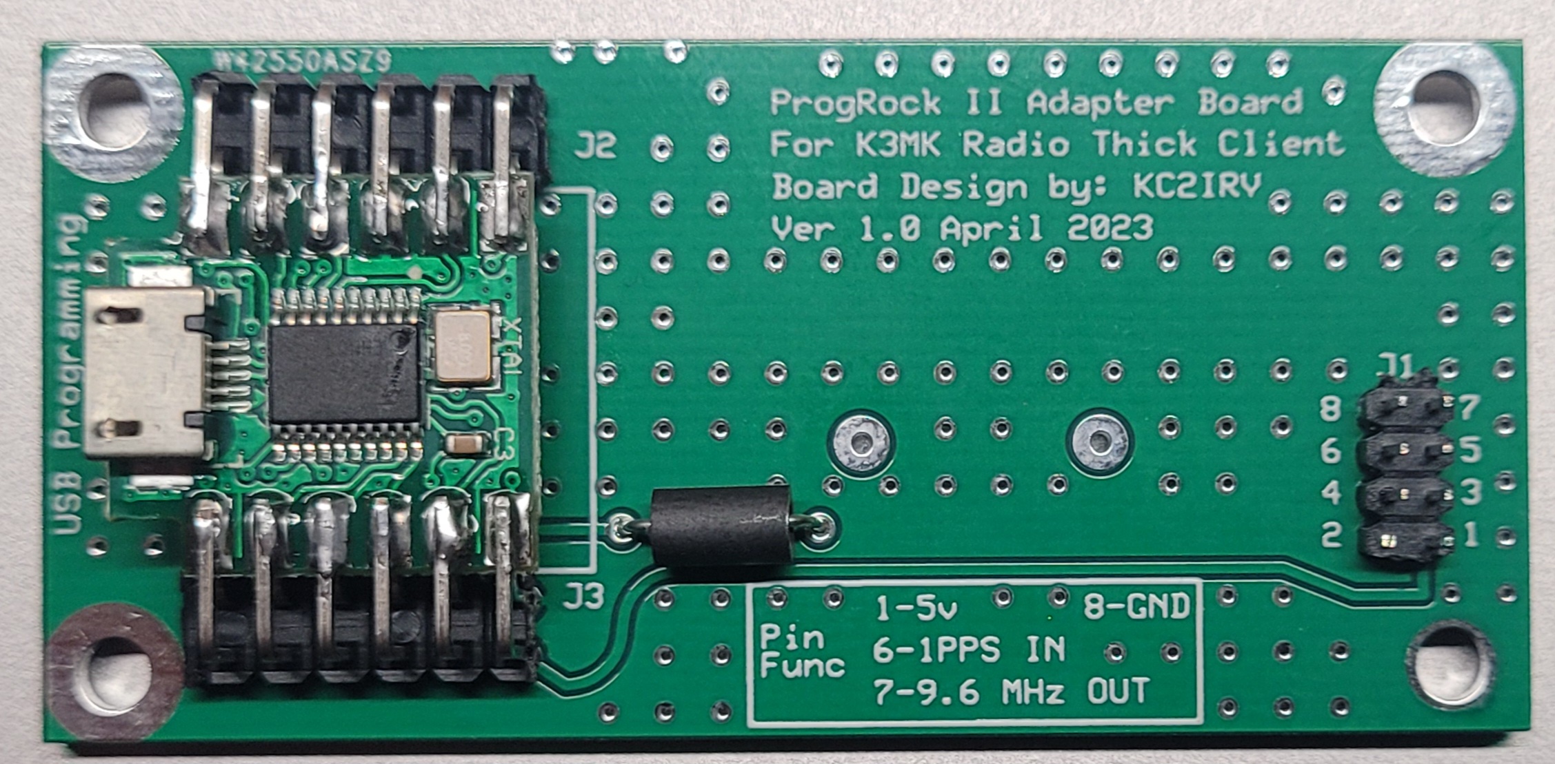
ProgRock II Adapter Board for Simulcast Operation
At the moment, I have designed my own plug in module that will provide the the 9.6 MHz to the PIC for simulcast operation. This module will discipline itself off of the 1PPS from the external GPS connected to the Thick Client Module. This module will produce the 9.6 MHz even without a GPS input if you are not simulcasting. The module I have designed is an adapter board for the QRP Labs ProgRock II. It will plug in to the board using two pin sockets, or soldered directly if you wish. I have the first prototype built at the moment and so far it's working as expected. On this current 1.0 version of the board I made a small error on the PCB. The error is that Pin #2 is tied to the ground plane of the board. If you build this board, all you need to do is cut off pin #2 from the pin header. Here are pictures of the first board I made.
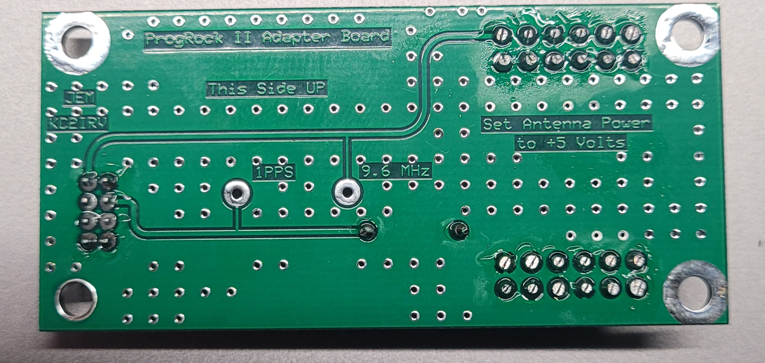
In order to use this board you need to remove the crystal X1 since it will no longer be needed since this board will provide the needed 9.6 MHz clock to the PIC. You also need to have capacitor C34 installed which is an 18pF ceramic capacitor. This couples the clock signal from the ProgRock II adapter board to the the PIC.
GPS and Console Data Jumper Settings
The documentation does not specify the data jumper settings for the board. I will be adding this information to the documentation package but I will also show them here.
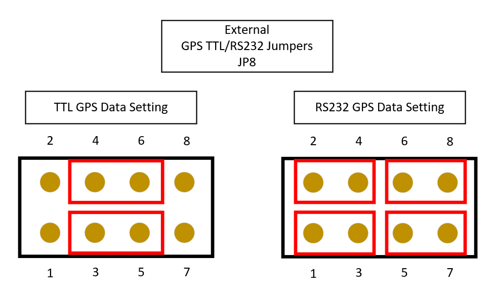
This is a diagram of the jumper J8. This selects the data level (either TTL or RS232) you intend to feed the board from an external GPS unit. The RTCM has this built in as well but the original Voter board can only be fed with RS232 levels. These jumper settings only effect the data for the external GPS unit, not the internal GPS module if you are using one.
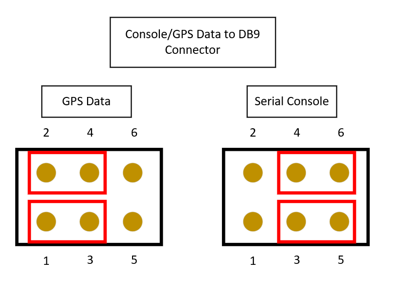
 This next set of jumpers, which is JP9, allows you to select whether you can access the console interface on the DB9 connector or if you wish to see the data from the GPS unit and also allow you to configure the GPS unit, if the GPS unit supports it.
Squelch Test Points
The Thick Client Module has 3 test points for easy access out of the front of the unit. The test points are as follows:

Test Point #1 - Squelch Audio just before it hits the Op-Amp to become the noise reference voltage.

Test Point #2 - Receive Audio Input to the squelch circuit. This test point lies just after the 20 dB jumper JU1 to increase the noise audio, so if this jumper is installed you would see a 20 dB increase in this reading.

Test Point #3 - Squelch noise voltage aka NVOLT. This is a DC voltage that indicates the level of noise on the receive signal.

Test Point #4 - Ground
Jumper and Switch Settings

SW1-1 - Initialize EEPROM
Initialize the configuration parameters in EEPROM (factory reset). If SW1-1 is in the ON (down) position when firmware starts, the operating parameters in the EEPROM will be set to default values. The HB LED (LED1, Red) will stay off for approx. 4 seconds, then stay on steady to indicate that the initialization process is complete. Afterwards, SW1-1 may be returned to the OFF (up) position and the system will continue running as usual. Note, if SW1-3 is in the ON (down) position during this procedure, the "Diode Calibration" process will also occur.

SW1-2 - Squelch Calibration
Flip ON (down) to calibrate squelch.

SW1-3 - Diode Calibration
Flip ON (down) to perform "Diode Calibration". This is a form of temperature compensation, where a power supply voltage is sampled that is dependent on the temperature coefficient of a diode.

SW1-4 - LED Receiver Level Mode
Flip ON (down) to re-purpose LED3 and LED4 to allow for visual indication of RX input level.

SW1-5 - LEDs On/Off
Flip OFF (up) to disable all LEDs.

JP1 - Output Amp Power Source
Selects power source for output audio amplifier. Pos 1 for 3.3v, pos 2 for 5v, pos 3 for 12v.
WARNING!!!
The current MCP6002 device does not support a Vcc voltage of +12VDC. I would advise the 12v
selection to not be used.

JP2 - External GPS ant power
1-2 for 5v, 2-3 for 3.3v

JP3 - Internal GPS ant power
1-2 for 5v, 2-3 for 3.3v

JP8 - GPS logic level selection
2-3 for TTL, 1-2 AND 3-4 for RS232

JP9 - Serial port mode selection
1-2 for GPS, 2-3 for console

JU1 - Discriminator Level Boost
Insert if low discriminator level. If squelch cannot self-calibrate with JU1 removed (too low), try with JU1 inserted. Note: this jumper affects the squelch calibration circuit only. Not to be confused with JU4, which is the pad for the receive audio.

JU4 - 20dB Pad
Insert to attenuate discriminator input level by 20db. This pad affects the receive audio level.