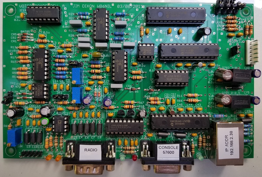
This is the original Voter Board designed by Jim Dixon WB6NIL (SK). This board doesn't look much like the RTCM but its functionality is identical to the RTCM. At this moment, if you want one of these boards they need to be built by you or someone you know. Unfortunately, due to the use of through hole components, some of the components are becoming harder to find but still available. I have built several of these boards and use them in my system along side some RTCM's. All of the information needed to build this board can be downloaded in this master file package which contains the CAD drawings, schematics, parts list and more HERE.
  In order to build this board, you need to have some decent soldering skills. All the components are through-hole so it's not too bad to build. Typically, this board can be completed in about 2 to 3 evenings worth of work.
One of the things that puts a lot of people off from building this board is the programming of the PIC with the software. This really isn't as difficult as it sounds, I made a video showing how to do it which should take some of the fear out of it.

YouTube - Programming the PIC on the Allstar Voter Board Video

The Voter Board VS The RTCM
As stated before, these two devices look very different but do the same job. There are some differences on the inside as far as the components. The RTCM and Voter Board use two slightly different micro-controllers. The Voter Board uses the MicroChip DSPIC33FJ128GP802 where the RTCM uses the MicroChip DSPIC33FJ128GP804 micro-controller. The main difference is the 804 version has more I/O's built in to it which eliminates the need for the MicroChip MCP23S17SP I/O expander that is required to be used with the 802 micro-controller. The difference in micro-controllers is what creates the need for two different versions of firmware. One of the other differences is the RTCM can use both TTL or RS232 NMEA GPS data which is jumper selectable where the Voter Board is designed for RS232 only.
The one disadvantage in my opinion is Micro Node International does not publish the schematic for the RTCM. Having the schematic available for the Voter Board and with how similar they are, it's not hard to reverse engineer a schematic for the RTCM. I have repaired a few RTCM's and other than the component ID's being different the RTCM seems to follow the Voter Board Schematic pretty closely. Another difference I will mention is that for things like the PTT output and LED drivers the RTCM uses MOSFET transistors and the Voter Board uses BJT transistors. I found this out because I had an RTCM where the PTT line stop working and I found the transistor not responding as it should. so I had to look up the device and found it to be a MOSFET. In my opinion, I would not have chosen MOSFETS for this task due to their static sensitivity but to be honest, I have only ever seen one RTCM experience this issue so it's really a non-issue as far as I'm concerned.

This is the pinout for the interface connectors of the Voter Board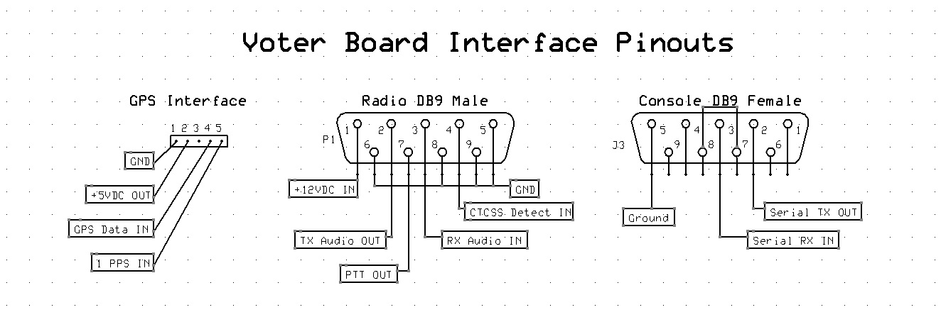
Voter Board Modification to Accept an External 9.6 MHz Reference
As stated in other places on this site, you will need to modify the Voter Board to accept an external 9.6 MHz reference if you wish to properly simulcast your system. This will require you to remove the crystal X1 which is right next to the PIC. My suggested way of connecting the external reference is using a very thin piece of coaxial cable such as RG316, connect the center conductor of the cable to one of the pads where the crystal used to be and connect the shield of the cable to a convenient board ground point. If you are using a Leo Bodnar unit as your reference, it is recommended that you place a capacitor such as a .1 uf ceramic cap in line with the center conductor of the RG316 cable. This is due to the Leo Bodnar units having a small DC voltage on their output which can damage the PIC. Another recommendation is a .1 uf ceramic capacitor be placed across the two pads where the crystal was soldered into the board. Sometimes but not always there are stability issues and sometimes the board has problems booting up properly. My theory on this is that the PIC isn't fond of the one side of the crystal reference input being un-terminated which may introduce noise on the reference input to the PIC. A .1 uf capacitor across where the crystal used to be solves this issue.
If everything is connected correctly your Voter Board should boot up normally